Appearance
Icons

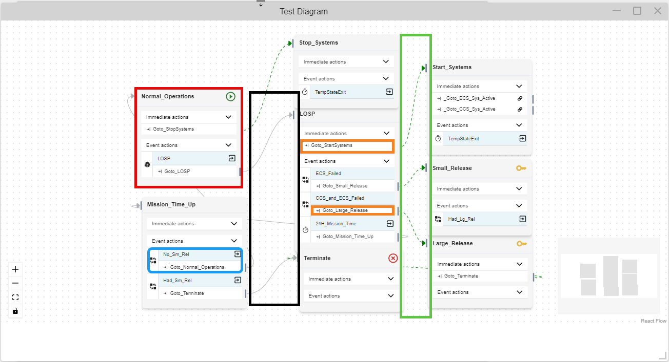
Diagram elements are tabulated by States, Events, Actions, and Arrows in the following four sections.
States
Icon | Description |
|---|---|
| Indicates a Key State | |
| Indicates a Start State | |
| Indicates a Terminal State |
See States for more information.
Events
Icon | Description |
|---|---|
| Variable Condition Icon | |
| State Change Icon | |
| Component Logic Icon | |
| External Simulation Icon | |
| Timer Icon | |
| Failure Rate Icon | |
| Distribution Rate Icon | |
| Exit Parent state when Event is triggered Icon |
See Events for more information.
Actions
Icon | Description |
|---|---|
| Action Type | |
| Transition Action | |
| Change Variable Value Action | |
| External Simulation Message Action | |
| Run Application Action | |
| Status Icons | |
| This click and drag from this icon to connect the action to a state. | |
| This icon appears instead of an arrow, when the transition goes to a state not in the current diagram. |
See Actions for more information.
Arrows
Icon | Description |
|---|---|
| Indicates a split or adding a new state to the "current states" list when the action is executed, while staying in the state with the event that occured. | |
| Indicates forced exititing from one state to another when the action is executed. |
See Arrows on the Diagrams page for more information.
Logic Trees

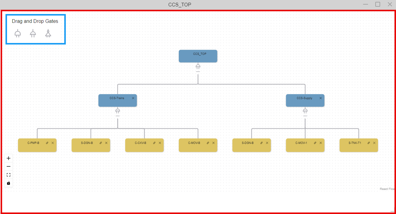
The icons from the Tools Window and the Editing Area are tabulated in the following two subsections.
See Logic Tree for more information.
Tools Window
Icon | Description |
|---|---|
| Logic Gates | |
| Drag this icon to add an Or Gate to the Fault Tree | |
| Drag this icon to add an And Gate to the Fault Tree | |
| Drag this icon to add a Not Gate to the Fault Tree |
Editing Area
Icon | Description |
|---|---|
| Or Gate | |
| And Gate | |
| Basic Event | |
| Click to edit the element | |
| Click to collapse the branches below the gate | |
| Click to expand the branches below the gate |