Appearance
States
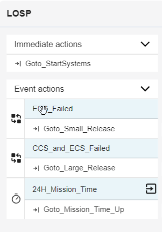
A state is a logical representation for the condition of a component, person, system, process, etc. Each state has a Name, Immediate Action, and Event Action section. There are four different kinds of states: Start, Standard, Key, and Terminal. The Header indicates what kind of state with an icon it is as well as the name of the state. The Immediate Action section lists actions taken when a new state is entered. The Event Action section lists events to look for when in this state and what action to take if the event is triggered.
Creating a New State
In the diagram that you want your state to be added to, right-click anywhere in the diagram window (not on any objects) and click, "New State." 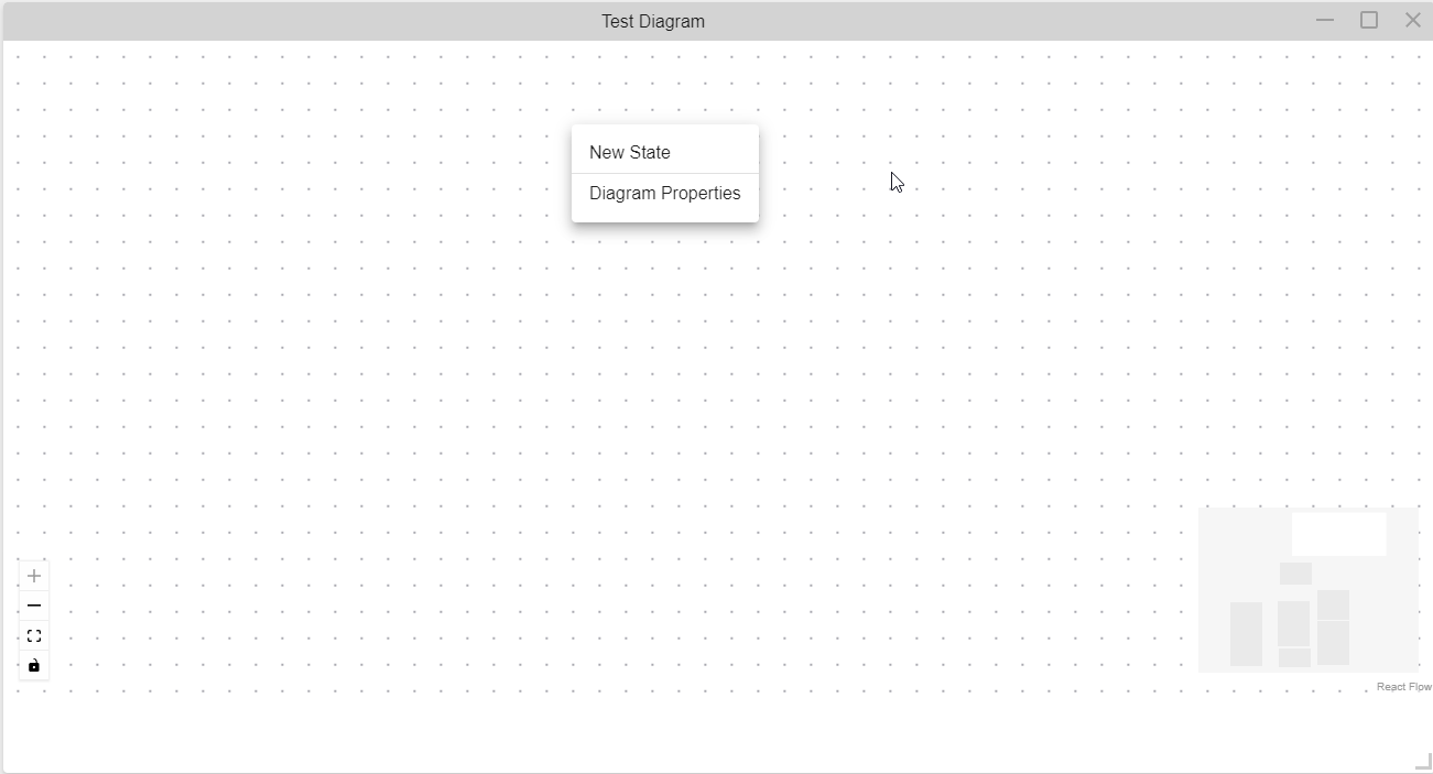
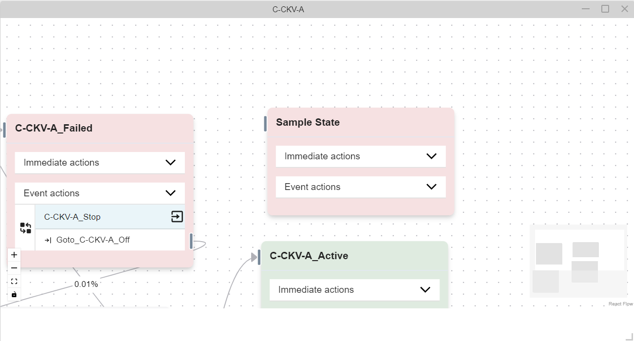
Type in a state name, an optional description, and, if the diagram is a single state diagram, what the logic tree evaluation should be. Press "SAVE". The state will open up in the diagram window in the Modeling Area.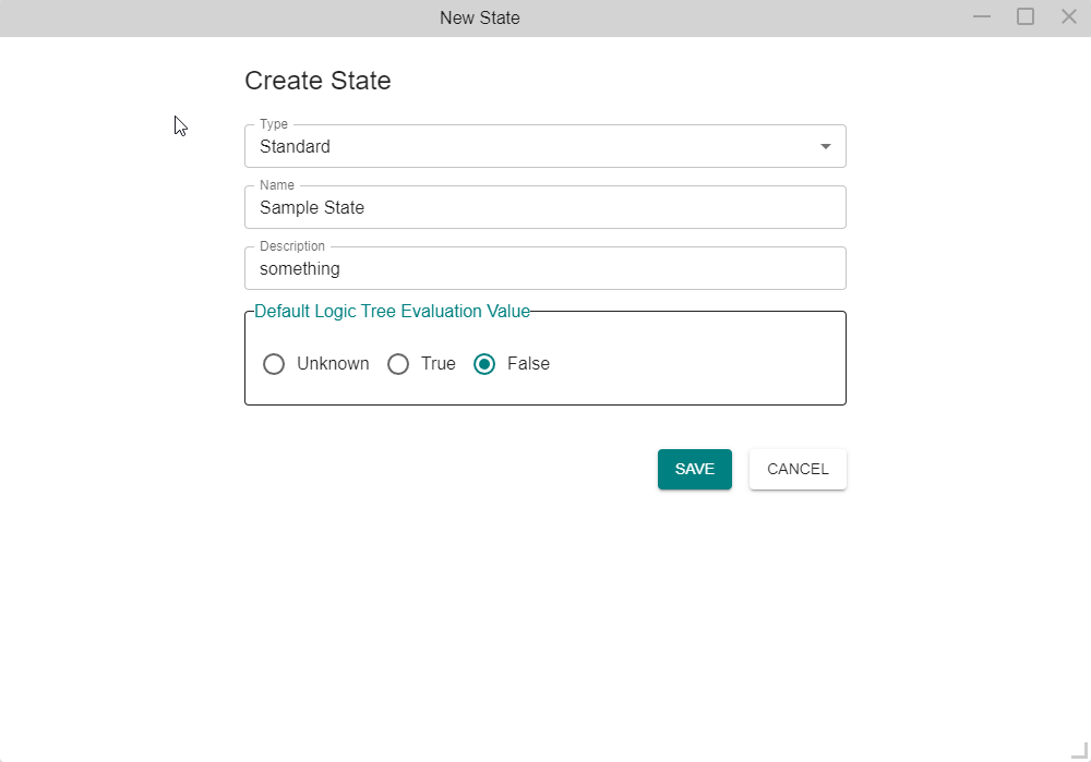
This name cannot be the same as any existing state in the model. If it is, an error message will pop up to notify you to choose another name.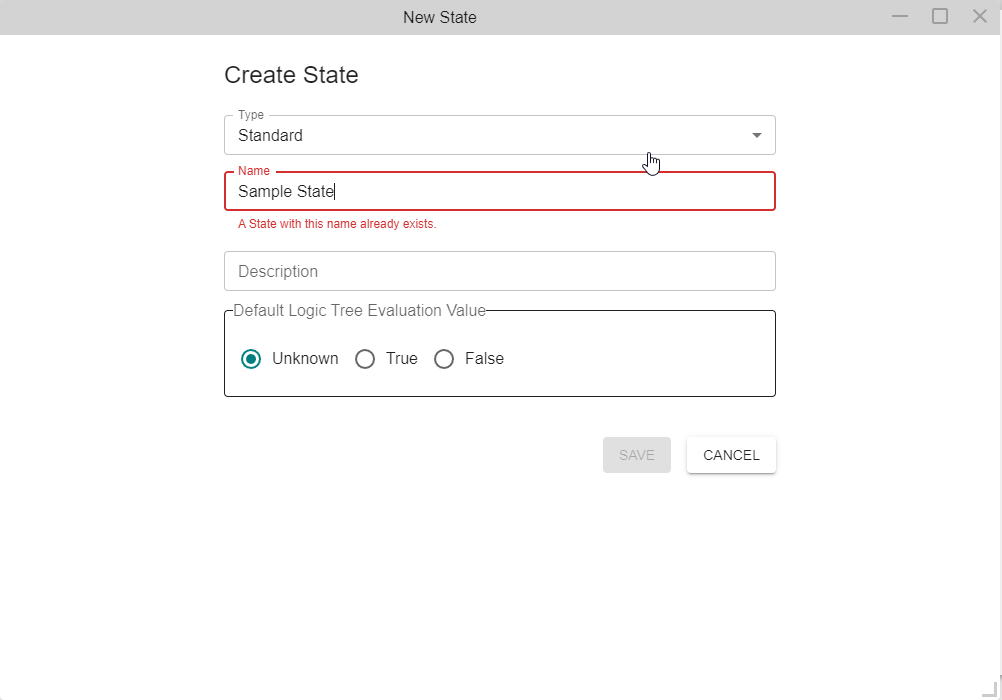
Editing a State
Option 1:
On the Left Navigation Frame, click on the tab (All or Local) where your state is located. If you are not sure which tab, click on the All tab. Right-click on the state and click "Edit Properties".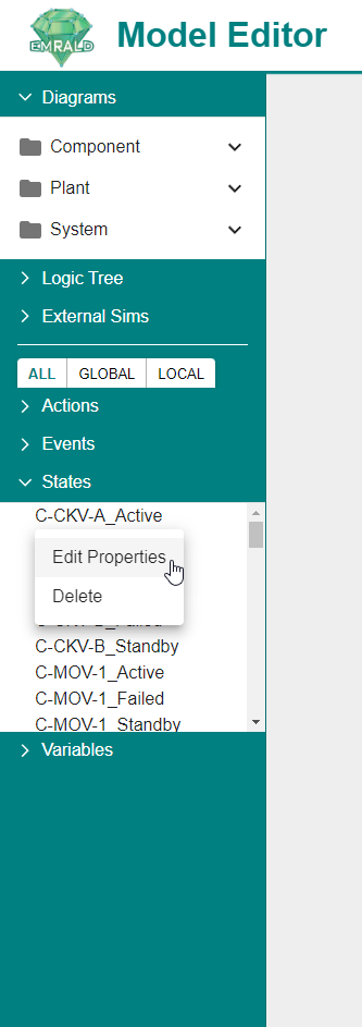
The properties window will open up in the Modeling Area. Note that because you are accessing the state properties from the Left Navigation Frame, the boolean evaluation value will not appear even if the diagram that the state belongs to is a single state diagram. Remember that states only evaluate to a boolean expression if the diagram it belongs to is a single state diagram. To view the boolean expression of the state, use option two for editing states.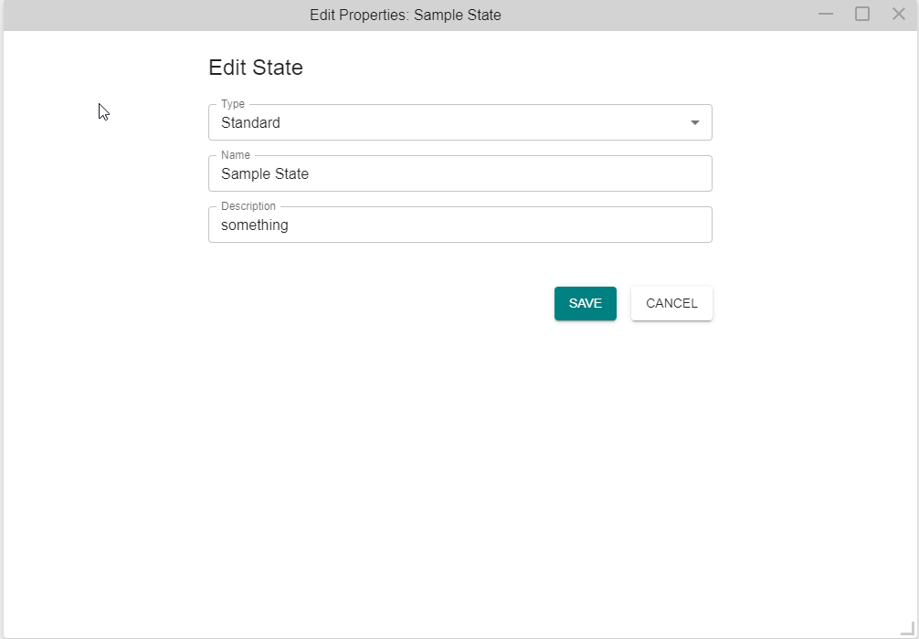
Option 2:
In the diagram window, right-click in the middle of the state and click "State Properties...".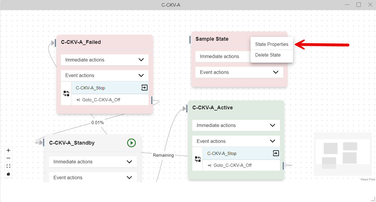
The properties window will open up in the diagram window. 
State Properties
State properties depend on the type of diagram. All diagram states have lists of events in the "Event Actions" list, and associated with each event is a "Exit Parent State" property. This property tells the simulation to exit the state after the events actions are executed. This adds a door with arrow icon (![]() ) to the right of the event and any arrows going from the action will turn black. If there are no transition actions.
) to the right of the event and any arrows going from the action will turn black. If there are no transition actions.
Note that the exit property is set and edited in the event forms, not the state forms. 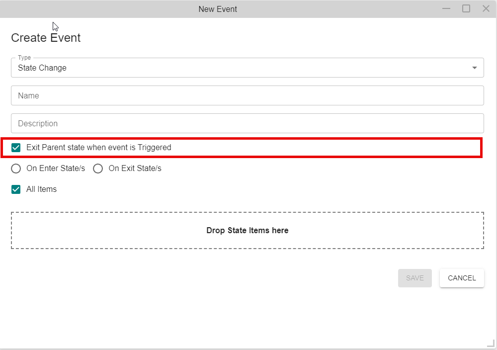
Single State Diagrams (System, Component)
Single State diagrams such as system and components have an additional status value. This field is used for logic tree evaluations. They must have at least one state with a "True" value and one with a "False". The "Unknown" value can be used if it is not to have any effect on the logic evaluation. See the following screenshots of the CCS System diagram as an example, there should never be a green dashed arrow in the diagram and the events for all transition actions should have a exit symbol.
The Single State diagram representing the CCS System. 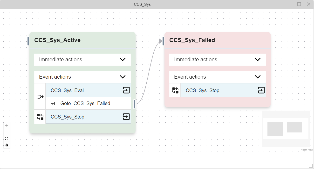
The CCS_Sys_Active State Properties window with "True" selected as the Status Value. 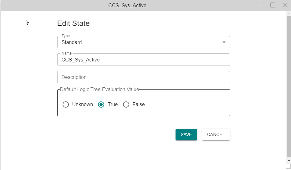
The CCS_Sys_Failed State Properties window with "False" selected as the Status Value. 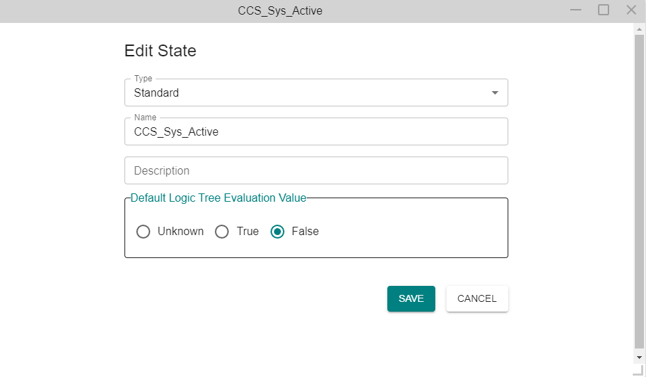
Deleting a State
Option 1:
On the Left Navigation Frame, click on the tab (All, Global, or Local) where your state is located. If you are not sure which tab, click on the All tab. Right-click on the state and click "Delete".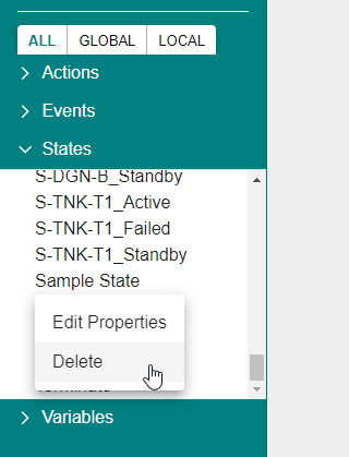
A confirmation window will appear in the Modeling Area. Click "DELETE".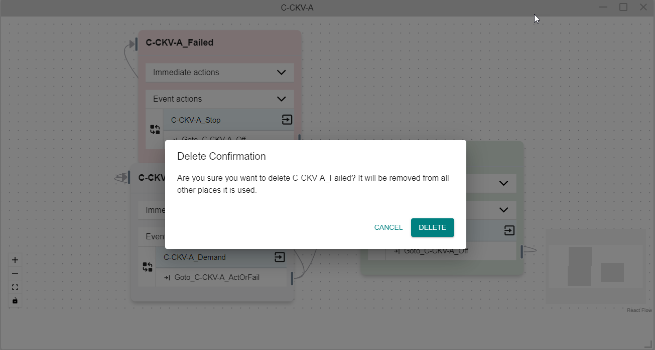
The state will be deleted and no longer listed in the Left Navigation Frame. 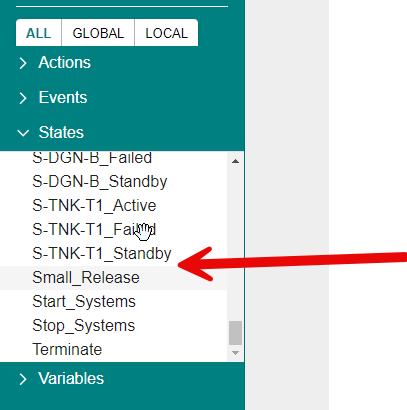
Option 2:
Open the Diagram containing the state and locate the state. Right-click on the state and click " Delete State".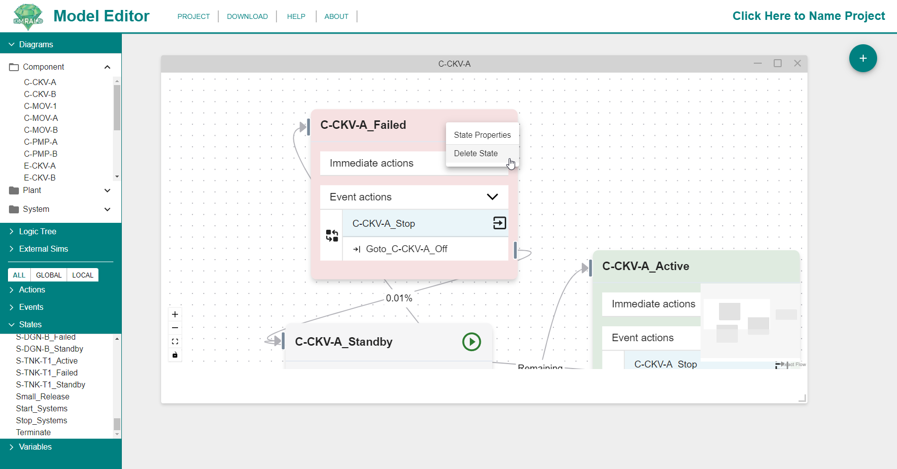
A confirmation window will appear in the Modeling Area. Click "DELETE".
The state will no longer show in the diagram window and no longer will be listed in the Left Navigation Frame. 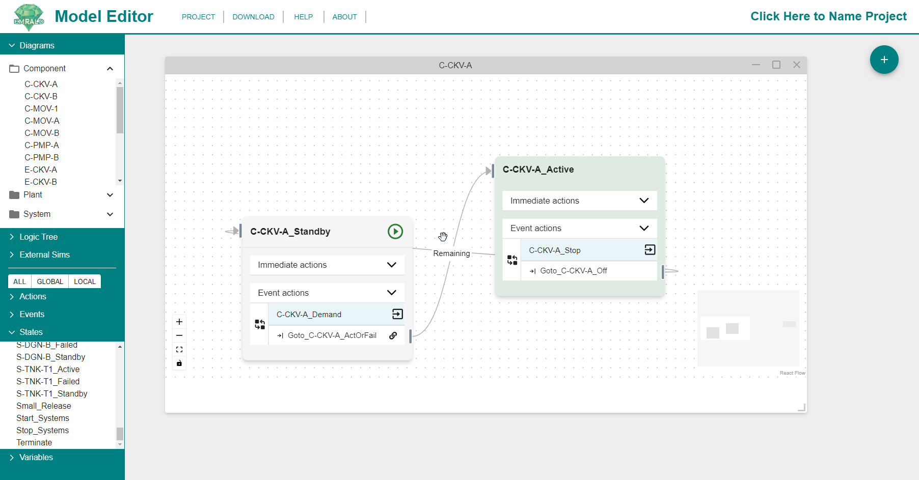
Types of States
The type of state will be indicated by an icon in the header of the state. Those icons are included in the title of the respective section as well as in the Icons: States section.
Start 
Start states are the states the model is in when the simulation begins. There must be at least one but can be more. All start states will be activated simultaneously.
Standard
A normal state representing no special conditions. It will have no icon in the Header.
Key 
A key state is what is of interest in the model, it will be tracked and reported if the model is in this state at the end of a simulation. In comparison to traditional PRA, all "End Sates" would have a corresponding "Key State." 
Terminal 
A user-defined simulation stopping point. A terminal state is not required but the simulation will run until the end time parameter is reached. However, it is recommend that terminal states be used to end all simulations when desired stop conditions are met for shortened computing time.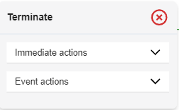
Immediate Actions
Immediate actions are actions that are executed upon entering the state in a simulation. The actions are performed in order, top to bottom.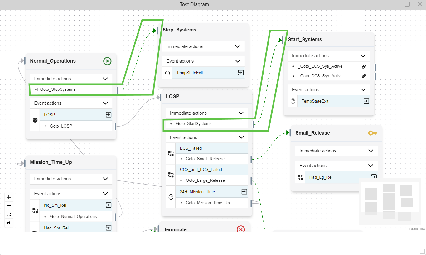
An icon on the left of the action shows what type of action it is. Refer to the Actions section of the Icons page to see what icons are associated with each action type.
Note
A Transition Action in Immediate Actions area can not exit the state (black arrow), but adds the "too" state as current state (dotted green arrow). See the Elements of a Diagram: Arrows section for more information.
Adding an Immediate Action
To add an Immediate Action, you can either...
Option 1: Right-click on the Immediate Action header in the state to create a new Immediate Action or 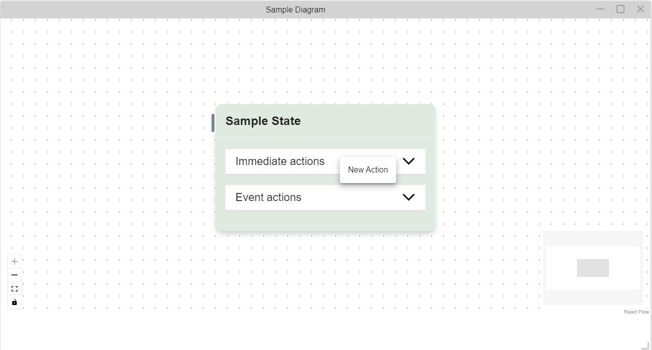
Option 2: Drag and drop an existing action into the Immediate Action section.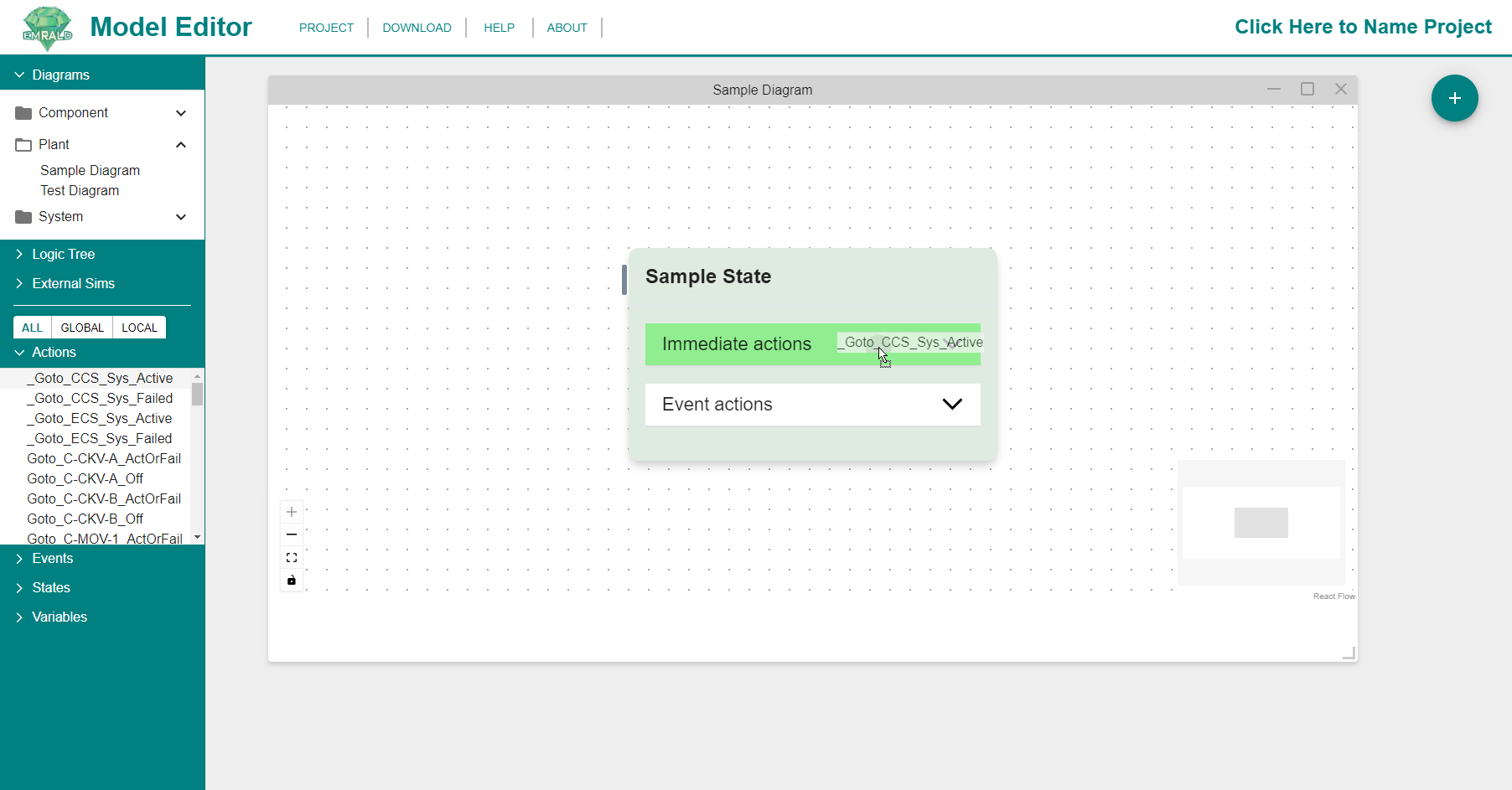
See Creating a New Action for detailed instructions for Option 1. See Adding an Existing Action for detailed instructions for Option 2.
See Actions for more information.
Event Actions
Event Actions are event/action combinations taken when the event condition is met. 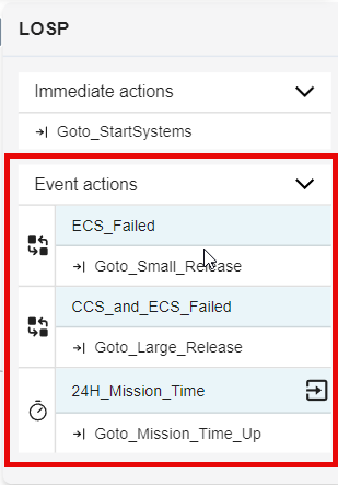
An icon on the left of the action shows what type of action it is. See Icons for descriptions of each icon.
Adding an Event
To add an Event, you can either...
Option 1: Right-click on the Event Actions header in the state to create a new event or 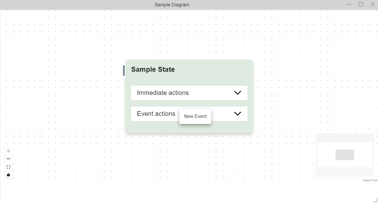
Option 2: Drag and drop an existing event into the Immediate Action section.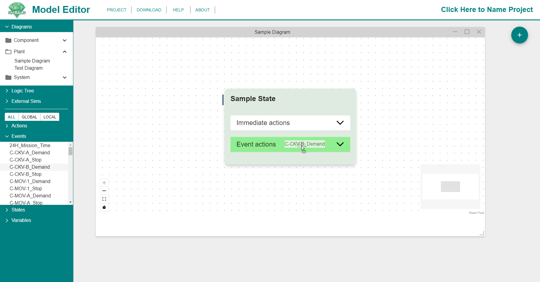
See Creating a New Event for detailed instructions for Option 1. See Adding an Existing Event for detailed instructions for Option 2.
See Events for more information.
Adding an Action for an Event
To add an action to an event, you can either...
Option 1: Under the Event Actions header, right-click on the event you want to add the action to create a new Event Action or 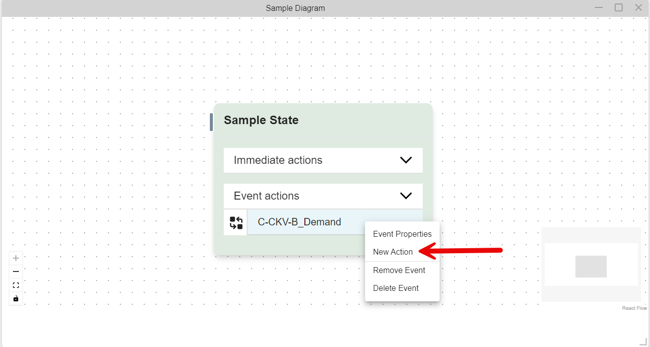
Option 2: Drag and drop an existing action into the Event Action section.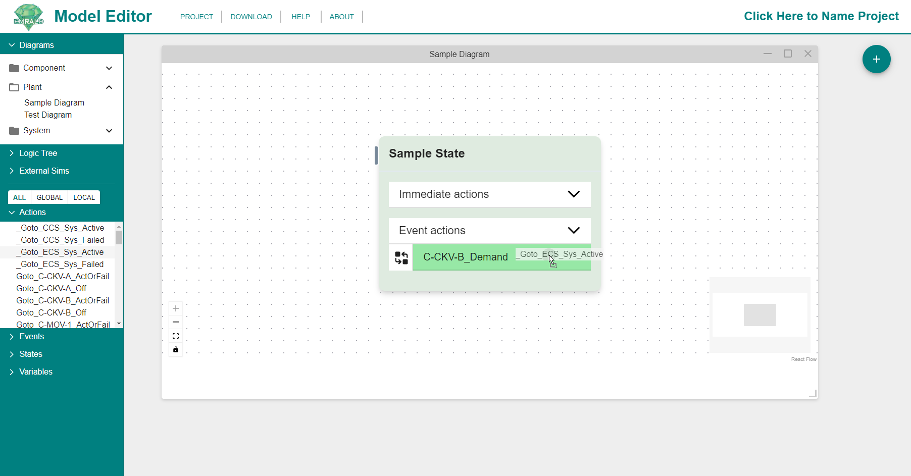
See Creating a New Action for detailed instructions for Option 1. See Adding an Existing Action for detailed instructions for Option 2.
See Actions for more information on Actions.