Appearance
Web User Interface
Initial Screen
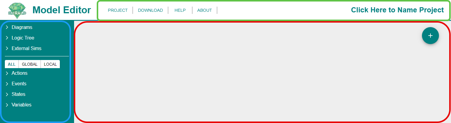
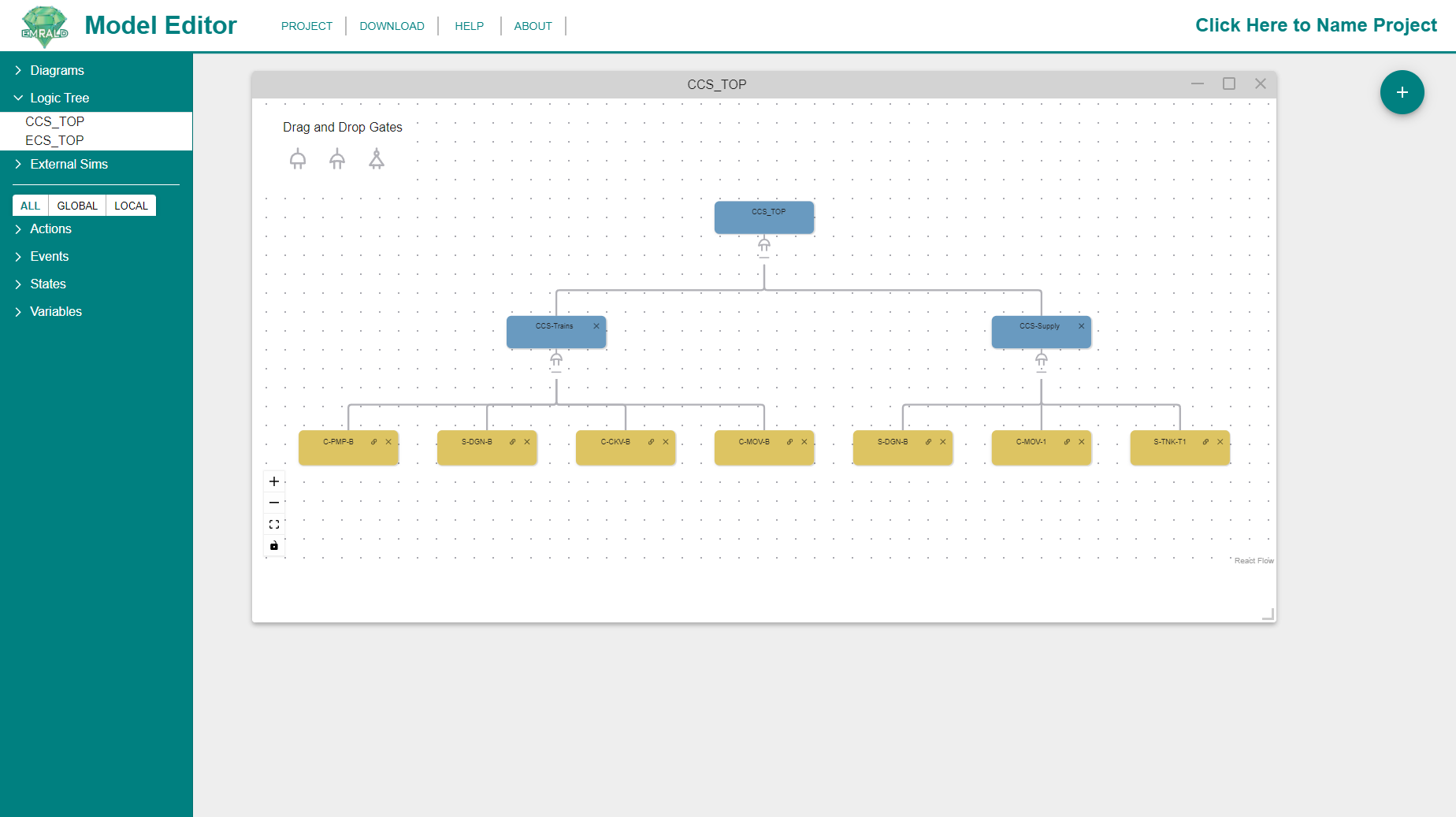
This is the screen you will see when you first open the EMRALD model editor. It contains the Modeling Area which is the main workspace, Top Menu Bar, and Left Navigation Frame which are editing and navigation panes that will be explained in the following sections.
Top Menu Bar
Project
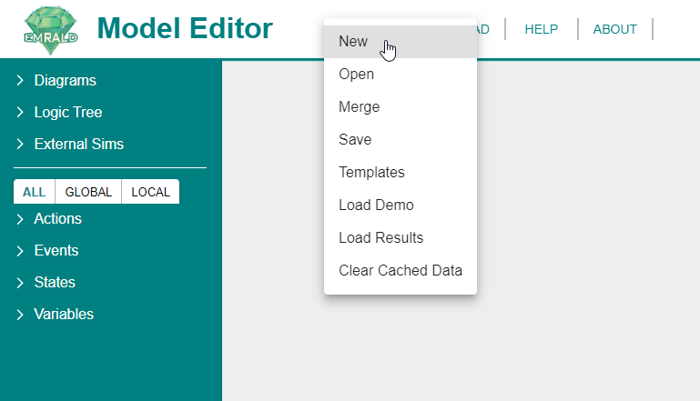
New: Creates a new project. It will clear the previous data from the system - including all states, diagrams, events, actions, etc... Make sure to have your previous project saved before clicking to start a new project.
To name your project, click on the "Click Here to Name Project" in the top right corner. It will bring up the following window where you can enter the project name and description.
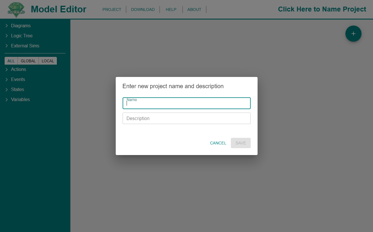
This will not change the name of the file or save a new version of the file. This will only change the name of the model as would be seen in the model's file.
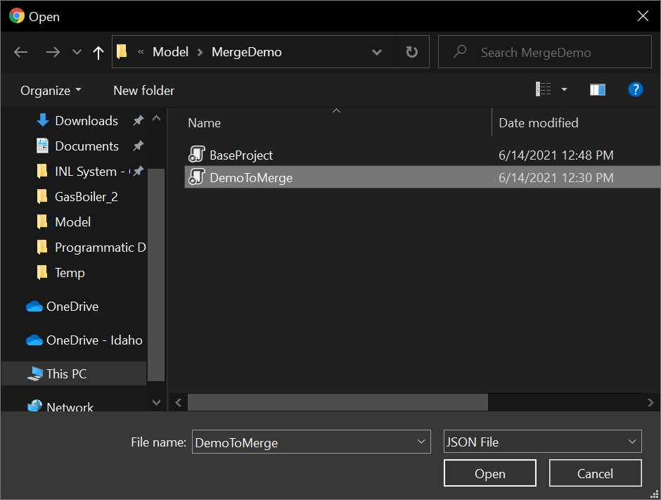
Merge: Merge one project into another project. This will pull in all diagrams, states, events, actions, variables, and logic trees into the project. First it will bring up a File Explorer, browse for the file you want to merge in and click "Open".
If there are diagrams or components with identical names in the models being merged, a conflict window will appear with a list of all of the identically named items. There are three options of how to resolve the conflict.
- Overwrite: The item being merged in will replace the item in the base project.
- Ignore: The item being merged in will be disregarded and the item in the base project will remain unchanged.
- Rename: The item being merged in can be renamed and made a new and separate item. A text box will appear in an adjacent column where you can edit the new name of the item being merged in.
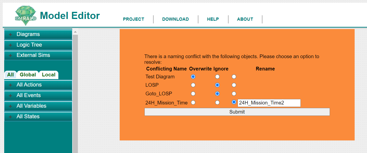
Once you complete your conflict resolution choices, click ""Submit"" and the model will merge into the base model accordingly.
- Open: Browse to open an existing project.
- Save: Operates like a standard "Save As" to save the current project.
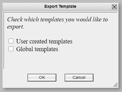
- Export Templates: Allows you to save any project template items for use in other projects. When clicked from the dropdown menu, the following window appears in the Modeling Area.
- Load Demo: Exits the current project and loads the demo project as with any changing of projects, unsaved changes in the current project would be lost.
Download
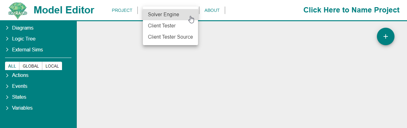
- Solver Engine: Downloads the EMRALD model solver which is a separate executable.
- Client Tester: Downloads an example test client that couples with EMRALD through message protocal. For use in testing and developing custom software coupling.
- Client Tester Source: Downloads the source code for the Client Tester.
Help 
Directs you to the main documentation page for the Emrald application, as shown below 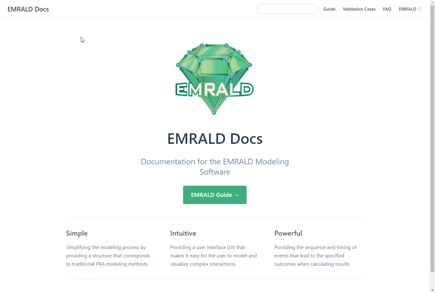
About 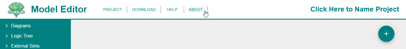
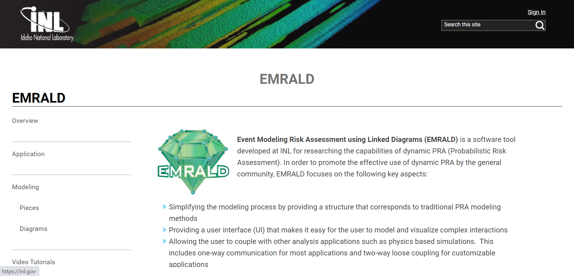
This redirects you to the INL EMRALD Website as shown below.
Left Navigation Frame
Modeling Structures
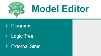
This top half of the Left Navigation Frame allows you to access your Diagrams, Logic Trees, and External Simulations.
Diagrams
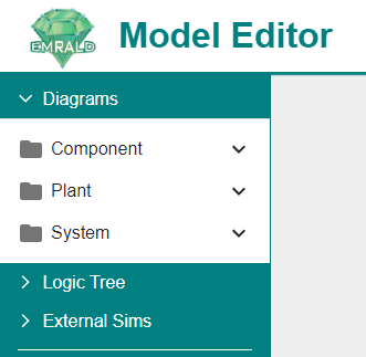
By default Diagrams are sorted by Plant, Component, and System Diagrams. However, these categories can be customized by the currently open model or for specific modeling needs. Double clicking on the folders will expand them to reveal the inidividual diagrams. Double clicking on the individual diagrams will open them in the Modeling Area.
Each diagram represents a particular piece of the model and the various conditions or states that this piece of the model can be in. These pieces correlate to aspects of traditional PRA modeling and range from small-scale components to a large scope, overall plant response and design. A diagram contains multiple states with the events that can occur, actions that can be executed and variables used. These all define how the simulation may sift through the diagram over time.
Additionally, some diagrams, Component and State, can also be evaluated to a Boolean depending on which stat they are currently in. This is a main feature that when combined with a Component Logic Event, can greatly simplify a model. Unlike the more general plant response diagrams, these diagrams are restricted to only be in one state at a time, in order to execute the evaluation process.
Breif descriptions of each diagram type will be explained below but for more information, see Diagrams.
Plant
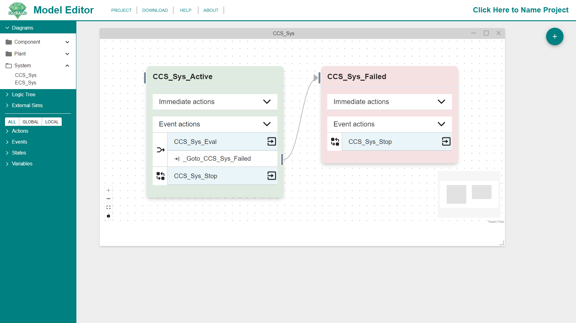
These diagrams are the main scenarios to be evaluated, similar to Event Trees in traditional PRA. This diagram has a starting state called Normal Operation. Other states do general evaluation and movement or be a key end state. Here the user defines the various states and events that drive the simulation from an initial start state and events to a desired key state.Component
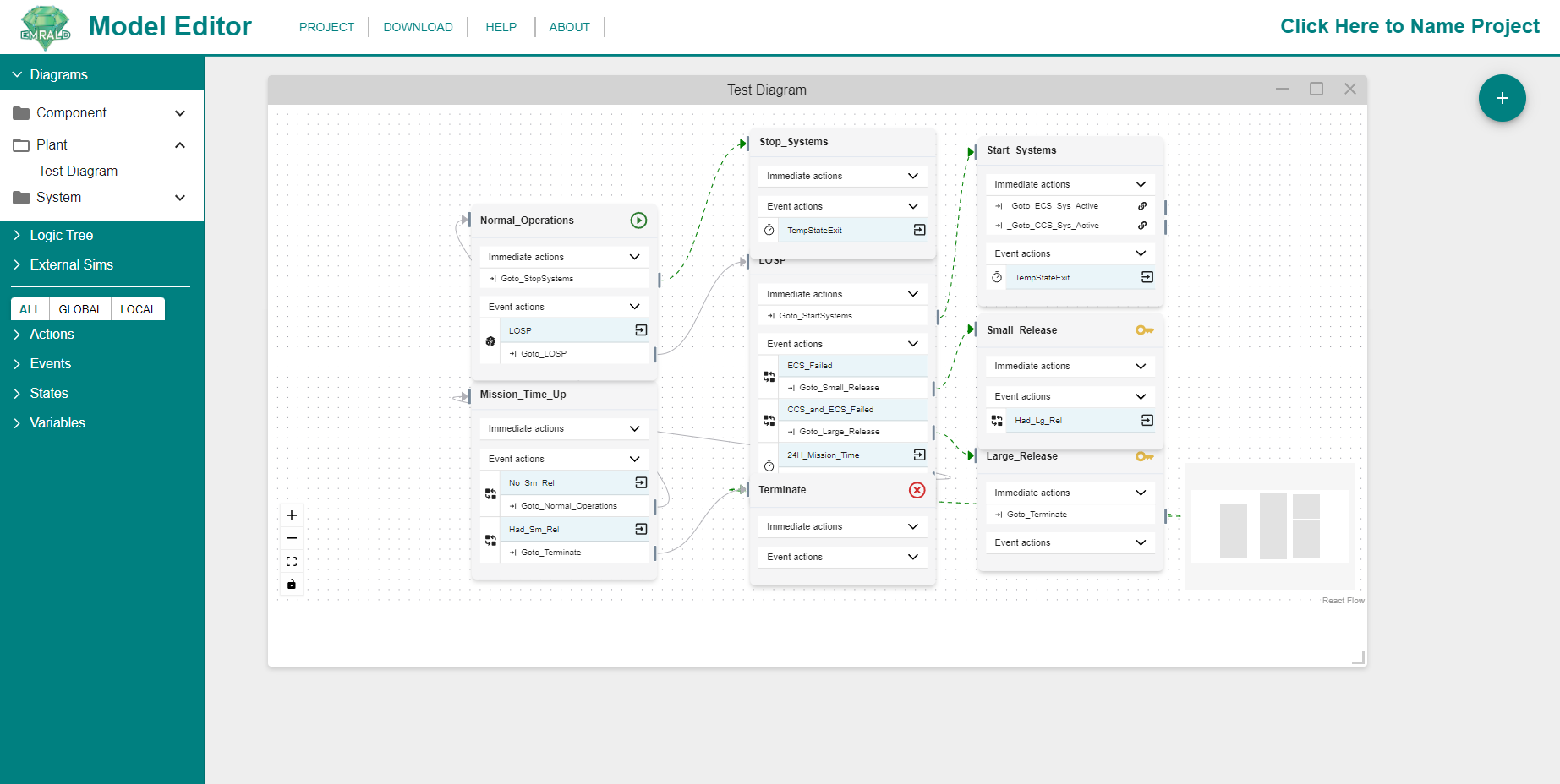
All aspects of a component should be captured in a simple Component Diagram. PRA Basic Events are captured by events in one of the component states. Events can be shared between different components for a "common cause" effect. Component diagrams are required to be "Single State Diagrams" meaning the simulation can only be in one of those states at any given time. Each State has a Boolean evaluation value, which can represent things like OK or Failed.System
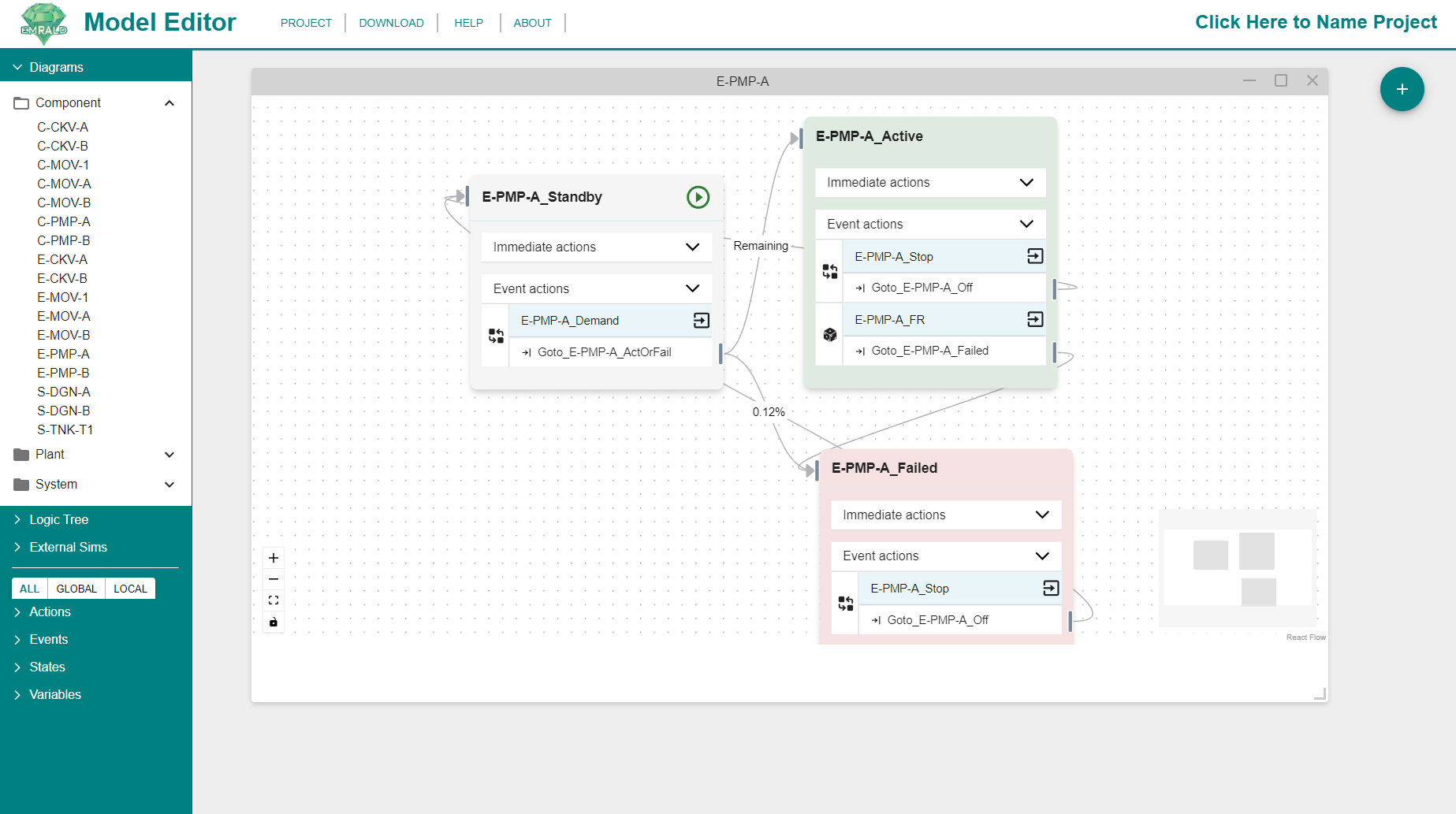
System Diagrams are mainly just a catigorization, but behave similarly to component diagrams. A Fault Tree from traditional modeling could be directly converted into System diagram with just two states and a "Component Logic" event used to determine the boolean logic from component diagrams. See Logic Trees and Events for more information. The two states for this diagram are "Active" and "Failed", with a "Component Logic" event in the active state evaluating the assigned logic whenever a component diagram state changes. If the logic ever evaluates to false, then the current state shifts from "Active" to "Failed". This is similar to a typical PRA model except the logic does not contain any probabilities, just references to the Component diagrams.
Logic Tree
All of logic trees are accessible in this section. Double clicking on the individual Logic Trees will open them in the Modeling Area.
Logic Trees utilize boolean gates to solve for the top value of the tree which can inform "Component Logic" events in diagrams.
See Logic Tree for more information.
External Sims
All of your external simulation links will be available in this section. 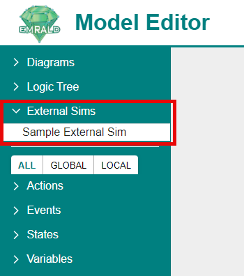
The External simulations are defined coupled links to an external code, such as physics models that inform the EMRALD model. This is used for special coupling cases to simply run an executable and process the results, use a "Run Application" action as described in the Run Application section of Types of Actions.
See External Simulations for more information.
Modeling Pieces Tabs
The bottom half of the Left Navigation Frame allows you to access your Actions, Events, Variables, and States which are organized by tabs. Actions, events, or states can be dragged from this Navigation Frame into applicable Modeling Areas for use in a diagram.
Tabs
All | Global | Local |
|---|---|---|
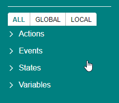 | 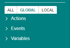 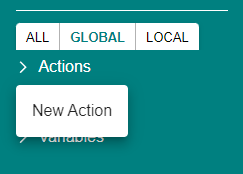 | 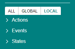 |
| Items from every diagram in the project. | Shows items can be used in any diagram. New Global items must be created through the right-click option of the selected type. Items created in a specific diagram are local to that diagram | Items present in the diagram currently open and being worked on. |
Actions
Actions change the properties or cause movement though a model during a simulation run.
See Actions for more information.
Events
Events monitor for specified criteria and can have one or more actions that are executed when that criteria is met.
See Events for more information.
Variables
Variables define a value that can be evaluated or modified by user defied scripts in some events and actions.
See Variables for more information.
States
States are a logical representation for a current condition in a diagram.
See States for more information.
Modeling Area
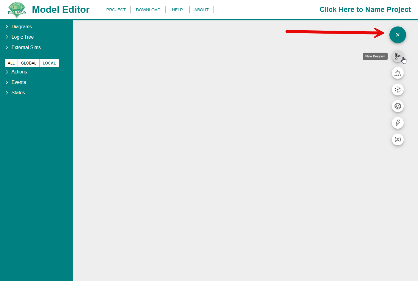
Drop Down Menu
The drop down menu, as shown below, is used to create diagrams, logic trees, actions, events, variables, and connect external simulations. Simply hover the mouse over the '+' icon and the menu will appear below. Although some of these can be created in other ways, this drop down is a simple tool that groups together creating each of these various parts. Each of these parts have their own section of documentation explaining it. Clicking on any option pulls up the form to create that part.